Karaoke Machine
In this project, I designed, simulated, and built a circuit to meet specific design criteria. The purpose of this device is to control audio and has several parts; an audio mixer and a function to enable karaoke. Through a series of component blocks you can choose whether to enable the mixer or karaoke function. Afterwards, three potentiometers allow you to set the desired bass, treble, and volume. The input and output of this device will be through audio input and output jacks, and the whole device will be powered by two 9V batteries. This device required prototyping with breadboards, soldering on a printed circuit board, and more.
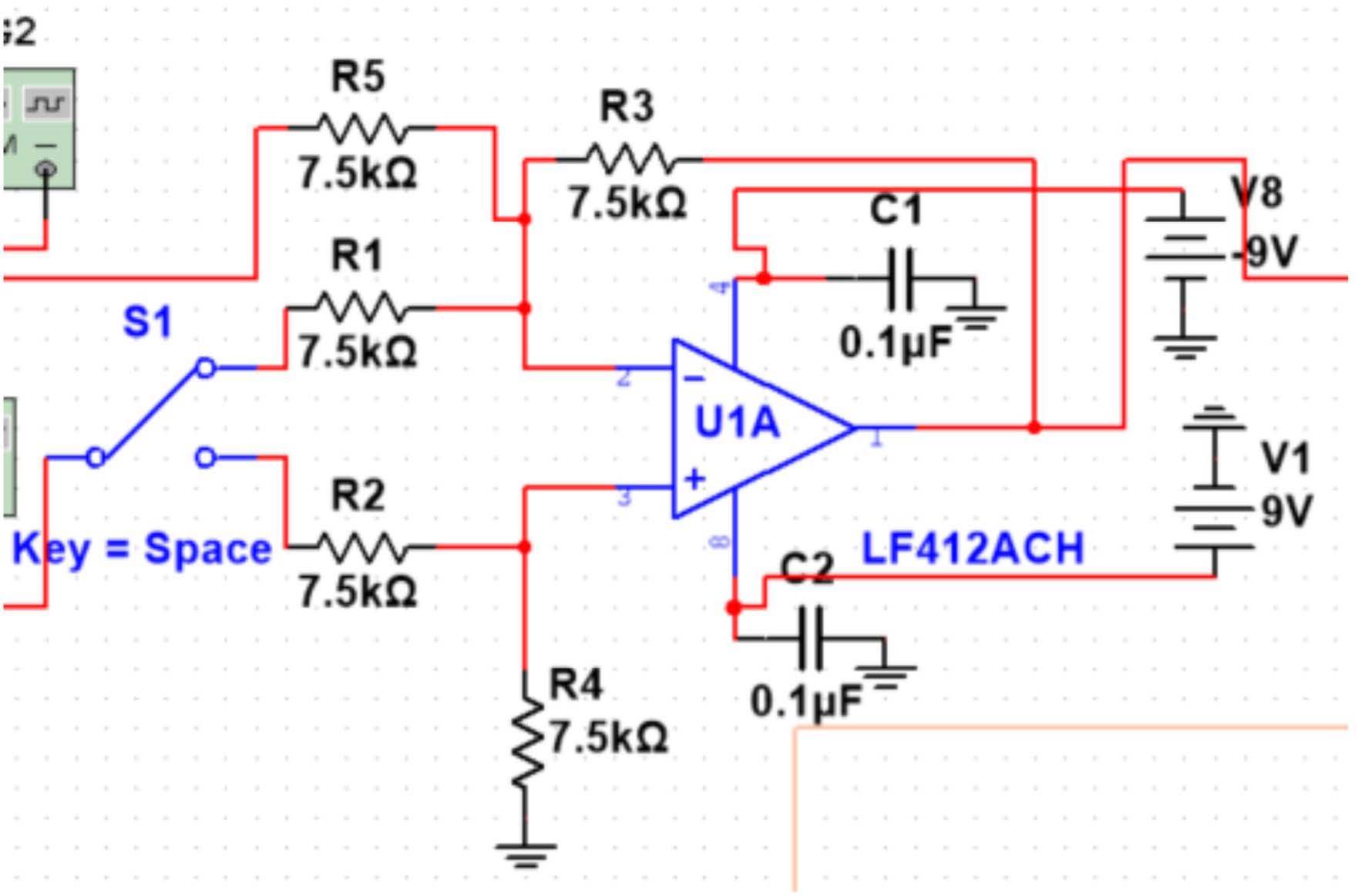
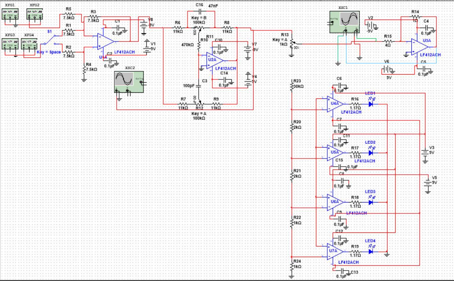
The circuit consists of 5 blocks, each with its own function in the overall system. The first block is a switch that controls whether the system is in mixer or karaoke mode, allowing the device to combine both audio channels or cancel one audio channel for karaoke mode. The second block uses a Baxandall filter for tone control, making the device able to adjust the bass and treble of the songs. The third block controls the volume of the device, while the fourth block shows the volume of the device visually using LEDs. Lastly, the fifth and final block is the output stage, which stabilizes the signal and ensures that it can be transferred to headphones or a speaker safely. These blocks all work together to produce a fully modular karaoke device.
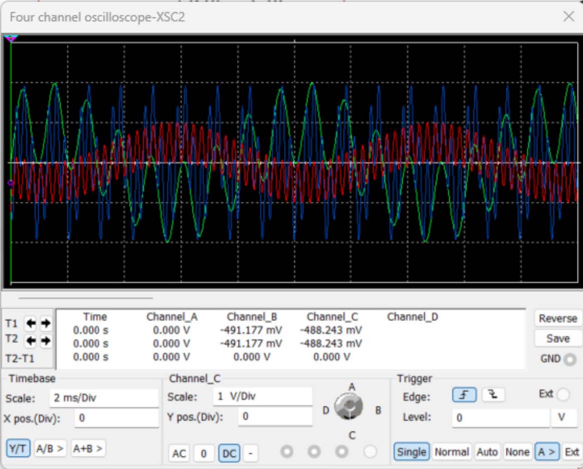
This device required thoughtful decisions about the circuit components and layout. For example, I used an inverting summing amplifier in the first block to achieve clear mixing and easy switching between modes, and selected very tight-tolerance resistors to process the audio signals as clearly as possible, resulting in a clear sound. For the second block, I chose the Baxandall circuit because of its smooth response across frequencies. The volume blocks were simple but effective, using a voltage divider for reliability and accuracy. To verify each step I used a simulation software, Multism, to check the functionality of my design, then the circuit was prototyped on a breadboard. Then I designed the PCB and soldered the verified components to it. This approach not only confirmed functionality but also gave flexibility to test and refine each block before the final integration.
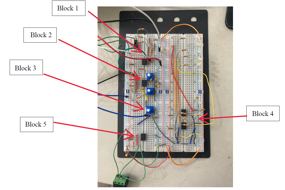
While this project was successful, it required problem-solving throughout the process. Early in the process, designing the circuits, calculating resistor values was challenging, requiring some trial and error. Another challenge was accounting for the difference in powering the circuit using a 9-volt battery instead of the 15-volt power source I was using earlier in the simulation. This required me to diagnose which resistors were causing problems and recalculate the correct values for them. Breadboard troubleshooting also required organization and attention to detail when it comes to wiring and component placement to ensure stable operation. Once these issues were resolved, the transition to the PCB was straightforward, and the final build performed as intended. Leading the device to work seamlessly.
This project helped strengthen many of my technical and problem-solving skills by going from a design to fully working hardware. I gained valuable experience in circuit design, breadboard prototyping, PCB assembly, soldering, debugging, and readapting designs when problems arise. However, the most important lesson I learned was how to take on a very complex project by breaking it up into smaller pieces, then integrating them into a cohesive system. These lessons that I learned give me the confidence to tackle any future engineering challenges with creativity and precision.